Project Overview
This project is about making an Arduino based Alarm clock using the DS3231 real-time clock module. This kind of project comes very cheaply at price, including all the hardware needed for the project. So, this one is a good project for school students, college seminars and people with the electronic gadget-building hobby. The real-time clock module itself is very cheap and works with I2C communication, so you can also use the same with other projects along with microcontrollers. The specific module which we are suing not only tells us the time but also tells us the temperature and also send a signal for any preset time, which signal can be used to trigger an attached buzzer to notify the time.
Hardware / Equipment Needed
- Arduino UNO is recommended as the main component
- One Buzzer module is a must
- One 10K potentiometer is needed
- Connecting wires & jumpers are needed obviously
- Breadboard for wire assembly
- One 16X2 LCD Module for displaying the time
- DS3231 RTC Module (also called Real-time Clock module)
- 220-ohm resistor needed
The working Principal of Arduino-based Alarm Clock
- As the DS3231 real-time clock module contains a built-in 3V battery, so the device keeps tracking the time even when not powered externally. To use the time data from the module and in order to make it work like an Alarm clock we will be using the library functions of Arduino IDE and then we will set the program to compare the time data with the alarm time that we have set in the program.
- In order to work perfectly, when the current time would match with the alarm time (preset in the code), the buzzer will start to beep. We would be setting the beeping time to be for 2 minutes in our code, but the variable values depend on the user, so you can set the same according to your wish. The time along with the date will be displayed on the LCD at the same time.
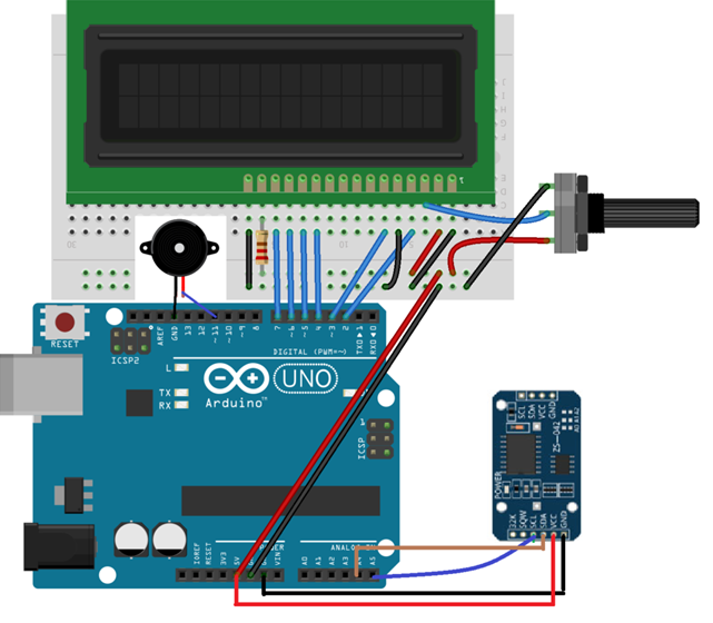
Circuit Assembly
To assemble all the equipment correctly follow the following instructions:
- Now you have to Connect the all the data pins (D4-D7) of the LCD module to the data pins of Arduino, which are pin no 4, 5, 6, 7 accordingly on Arduino.
- Point out the Pin no 15, which is for the 5V pin on the Arduino through the 220-ohm resistor as the positive backlight pin
- The next pin which is Pin no 16 is for Ground on the Arduino as the negative backlight pin, so connect accordingly.
- Starting from the left side Pin no 1 on the LCD module is for ground on the Arduino.
- The next Pin no 2 on the LCD module is for 5V connection on the Arduino.
- The next Pin no 3 on the LCD module is meant to be connected with the middle pin on the 10K potentiometer.
- Pin no 4 on the LCD module is for digital pin no 2 on the Arduino, so connect accordingly.
- Now the Pin no 5 on the LCD module is for the ground of Arduino. This will put the LCD in reading mode.
- And the Pin no 6 on the LCD module is meant to connect with the pin no 3 of Arduino.
Now connect the DS3231 Real Time Clock Module to the Arduino as per the instructions:
- Now connect the GND on the DS3231 to GND on the Arduino
- Then connect the VCC on the DS3231 to the 5V pin on the Arduino
- Now you have to connect the SCL on the DS3231 to A5 on the Arduino
- At last, you have to connect SDA on the DS3231 to A4 on the Arduino
In the end, connect the positive pin of the buzzer to pin 11 on the Arduino and also the negative pin of the buzzer to GND pin on the Arduino.
Circuit Diagram CGI
Arduino-based Alarm Clock Code for Arduino IDE
If you are not comfortable with coding like many others, then just copy the below code to your Arduino IDE and save it, then try to compile it, hope it will work flawlessly, as the code is already been tested by myself. If you are comfortable with Arduino IDE coding, then modify the below code as per your need. Do not worry about copyright or plagiarism if you are about to submit the code in some seminar, as with Arduino IDE and with the help of GitHub all these are open source codes just like Arduino IDE itself.
#include <DS3231.h>
#include <Wire.h>
#include <LiquidCrystal.h>

LiquidCrystal lcd(2, 3, 4, 5, 6, 7);
DS3231  rtc(SDA, SCL);
Time  t;
#define buz 11

int Hor;
int Min;
int Sec;


void setup()

{

  Wire.begin();
  rtc.begin();
  Serial.begin(9600);
  pinMode(buz, OUTPUT);
  lcd.begin(16,2);
  lcd.setCursor(0,0);
  lcd.print("DIYHacking.com");
  lcd.setCursor(0,1);
  lcd.print("Arduino Alarm ");

  // The following lines can be uncommented to set the date and time
  //rtc.setDOW(WEDNESDAY);     // Set Day-of-Week to SUNDAY
  //rtc.setTime(12, 0, 0);     // Set the time to 12:00:00 (24hr format)
  //rtc.setDate(1, 1, 2014);   // Set the date to January 1st, 2014

  delay(2000);
}
void loop()
{
  t = rtc.getTime();
  Hor = t.hour;
  Min = t.min;
  Sec = t.sec;
  lcd.setCursor(0,0);
  lcd.print("Time: ");
  lcd.print(rtc.getTimeStr());
  lcd.setCursor(0,1);
  lcd.print("Date: ");
  lcd.print(rtc.getDateStr());

 if( Hor == 11 &&  (Min == 32 || Min == 33)) //Comparing the current time with the Alarm time

{
Buzzer();
Buzzer();
lcd.clear();
lcd.print("Alarm ON");
lcd.setCursor(0,1);
lcd.print("Alarming");
Buzzer();
Buzzer();
}
delay(1000);
}

void Buzzer()
{
digitalWrite(buz,HIGH);
delay(500);
digitalWrite(buz, LOW);
delay(500);
}
Code Explanation & Working Principal
- At first, we comprised the libraries for the DS3231 real-time clock and the LCD. The wire library is for enabling the I2C communication between the DS3231 and the Arduino microcontroller. The DS3231 real-time clock communicates with the Arduino through the I2C communication, so we have included the wire library as standard.
#include <DS3231.h>
#include <Wire.h>
#include <LiquidCrystal.h>
- After that, we initialized the variables that we are going to use in this code.
LiquidCrystal lcd(2, 3, 4, 5, 6, 7);
DS3231  rtc(SDA, SCL);
Time  t;
#define buz 11
int Hor;
int Min;
int Sec;
- The below code line are actually commented in the code already. These traces are for setting the date and time for the RTC module. You won’t need to set the date and time each time you operate it, due to the fact the RTC module has a battery that keeps operating even when the module isn’t always powered.
//rtc.setDOW(WEDNESDAY);     // Set Day-of-Week to SUNDAY
//rtc.setTime(12, 0, 0);     // Set the time to 12:00:00 (24hr format)
//rtc.setDate(1, 1, 2014);   // Set the date to January 1st, 2014
- In the loop function, we get the time from the module and store it in the variables. We will examine those variables later with the alarm time we want to set.
t = rtc.getTime();
Hor = t.hour;
Min = t.min;
Sec = t.sec;
- After that, we print the time and date on the LCD screen.
lcd.setCursor(0,0);
lcd.print("Time: ");
lcd.print(rtc.getTimeStr());
lcd.setCursor(0,1);
lcd.print("Date: ");
lcd.print(rtc.getDateStr());
- Then we examine the present-day time with the alarm time, and if the time matches, the buzzer will begin to beep. The buzzer will preserve on beeping for two minutes, but you may growth or lower the beeping time as a good deal you want.
if( Hor == 11 &&  (Min == 32 || Min == 33)) //Comparing the current time with the Alarm time
{
Buzzer();
Buzzer();
lcd.clear();
lcd.print("Alarm ON");
lcd.setCursor(0,1);
lcd.print("Alarming");
Buzzer();
Buzzer();
}
Conclusion
Built with Arduino, play with it to learn and Enjoy.
Related Posts
Finding Visual Studio Code Version on Windows 11 or 10
Running PHP Files in Visual Studio Code with XAMPP: A Step-by-Step Guide
Multiple Methods to Verify Python Installation on Windows 11
Single Command to install Android studio on Windows 11 or 10
How to Install and Use Github Copilot in JetBrains IntelliJ idea
How to Enable GitHub Copilot in Visual Studio Code