So here is the tutorial, where I will discuss how you can get started with Multisim, which is one of the best electronic circuit simulator software available and will also discuss how you can simulate electronic circuits using the software.
From our smartphones to the computer that we use, and every other electronic gadget to accomplish a lot of small tasks, there is one thing in common. They all have electronic circuits, which include microprocessors, microcontrollers and small other circuits that help the gadgets do the magic. If you are into Electronics, a professional, hobbyist or a student, playing with electronic circuits is something that you have to do almost every single day and things might not go perfectly every time. In the worst-case, the circuit might go out on smoke and at other times, you might not get the appropriate output for which you have designed the circuit. Yes, life seems frustrating at times!
That’s when simulation plays an important role. If you are reading this article, you might already know about what simulation is all about, but let me explain it in one line. Simulation is a kind of a virtual arrangement where you can have an idea of how a system will function when it is implemented in real life. That’s the simplest definition of simulation and it varies depending upon what you want to simulate. So if you are working with electronics, simulation can save both your money and time and help you check whether you are getting the appropriate outputs before you can proceed with actually building a circuit from scratch. Just in case things don’t go as planned, you can again make the necessary modifications and find out whether it is working, to give your circuit a final shot.
What is Ni-MultiSim?
The NI Multisim is a simulation software for professionals, students and Educational purpose. It is a complete package to perform different exercises on electronic circuits. Multisim has an integrated chain of tools for circuit detection, simulation and layout allows the interdisciplinary use of the product. Seamless integration with NI Multisim optimizes the design experience, ensuring you can easily transfer schematics to PCB design and effortlessly annotate changes between layout and capture. With a comprehensive component library of components, whose characteristics correspond to the real components, circuits from analogue and digital circuit technology, mechatronics, microcontroller technology, Function generator, oscilloscope, logic or spectrum analyzer, in combination with interactive components, simulation are possible.
It is available in multiple editions, the Multisim for Education comes with 30+ intuitive simulated instruments, 20+ easy-to-configure analyses, and interactive components. Educational entities can use this circuiting software to teach analogue and digital circuit technology and power electronics in classroom and laboratory exercises. Students can retrieve designs from NI Multisim interactive SPICE-based simulation or from scratch using parts from the built-in Ultiboard database.
Available in two versions Mutlisim for Education and Multisim for Designers, of course, the designer one comes with extra features and capabilities such as 19,000+ Components Verified by Semiconductor Manufacturers; advanced Power Design With MOSFETs and IGBTs From NXP and International Rectifier; Multisim and Ultiboard Training Classes and more…
Before purchasing the Trial version is available to experience it.
MultiSim Supported Operating Systems:
- Windows 10
- Windows 7 (SP1) 32-bit
- Windows 7 (SP1) 64-bit
- Windows 8.1
- Windows Embedded Standard 7 (SP1)
- Windows Server 2008 R2 (SP1) 64-bit
- Windows Server 2012 R2 64-bit
Downloading, installing and using Multisim
Step 1: You can purchase and get a license for Multisim from here, and if you already have a license, you can download a copy or trial version of Multisim from here.
Step 2: Once downloaded, the installation of Multisim is the same as the installation of other Windows programs.
So, after the installation of the program is complete, it is time I should talk about how you can start stimulating your electronic circuits.
Step 3: Just open NI Multisim from your desktop or simply by searching for the same on your Windows start menu.
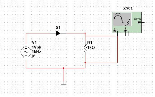
Step 4: I will show you, how you can build and simulate a half-wave rectifier using Multisim. A half-wave rectifier is the most rudimentary circuit to convert AC or alternating current to DC or direct current.
I will not keep any kind of filters and other sophistication within the circuit, as I just want to show you, how you can deal with circuits on Multisim, and proceed with even bigger projects.
Step 5: In this circuit, for making a half-wave rectifier, I will need 5 elements, a diode, an AC voltage source, a resistor as the load; a ground, and the cathode ray oscilloscope (CRO) or simply an oscilloscope.
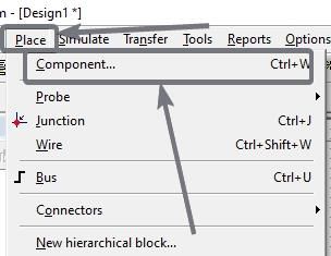
Step 6: Let me start by adding the necessary elements for making the circuit. Simply use the shortcut key combination ‘Ctrl+W’ or click on ‘Component…’ under the ‘Place’ tab to find a list of elements that is available within the program.
Step 7: I will recommend you to use the shortcut key combination as it will be handy, and adding electronic components is something that you will need every time on Multisim.
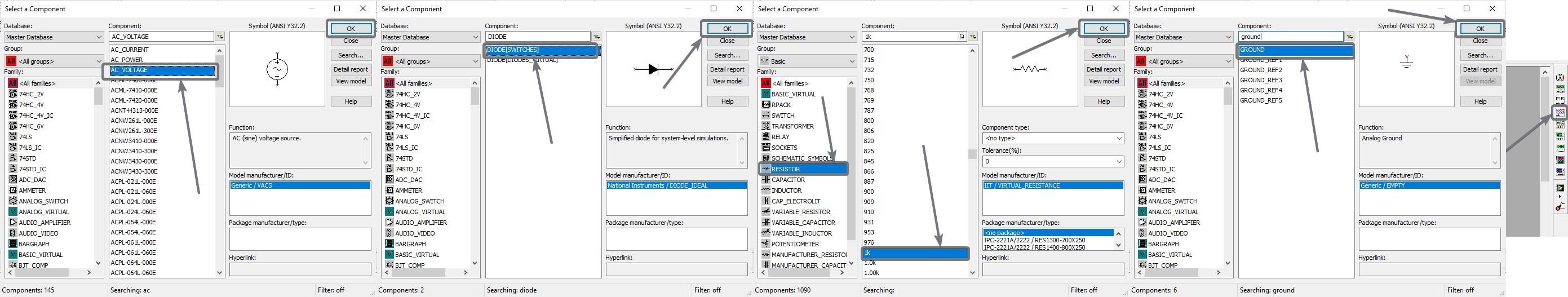
Step 8: Just type in the element that you need, in the search box, and add the appropriate element to your circuit. I am adding the four elements by searching for them in the search box. I am using a 1 k Ohm or a 1,000 Ohm resistor as a load. You can even use a different value.
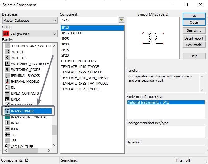
Step 9: If you can’t find the element that you are looking for, just select the appropriate group to find the element. For example, if you are looking for a transformer, just select the group ‘TRANSFORMER’ and place the appropriate one.
Step 10: To add the elements, just select the element you want to add and click on ‘OK’. Now drop it anywhere within the area as per your requirements.
Step 11: Once you are done adding all the elements, simply click on ‘Close’ to exit the component window, and proceed with connecting the elements.
Step 12: Now simply connect the ends, as per your circuit diagram, by clicking on one end of the element, and then by releasing the click, where it is to be connected.

Step 13: Keep doing this, unless your circuit is complete. My half-wave rectifier is complete now.
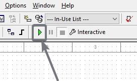
Step 14: To start simulating the circuit, click on the ‘Run’ button, or simply hit the ‘F5’ button.
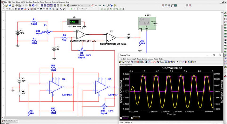
Step 15: Depending upon your circuit, you can see the output in a digital display, voltmeter, ammeter, or any other element. My output will be on the oscilloscope, and to find that, I will have to double-click to see the wave-form.
Here is the output wave-form, which is the same as the output generated by a half-wave rectifier.
You can even adjust the scale and get the output exactly the way you will see in a lab, with the abundance of options that are available in the oscilloscope window.

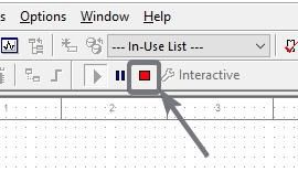
Step 16: To stop the simulation, just click on the ‘Stop’ button. You can even ‘Pause’ the simulation in between if you want to.
Step 17: You can even double-click on most elements to change the parameters. For example, you can double click on the ‘AC Voltage’ element to change the peak voltage, frequency, damping factor, delay, phase, and other perimeters.

You can repeat the same with other elements in the circuit, as well.
Multisim is a pretty powerful program, and you can even simulate the microcontroller-based circuits, as well, with Multisim. I will cover them in the coming days for sure.
Well, the simulation on Multisim might not be 100% accurate, as the electronic components available in the market aren’t perfect. Multisim will automatically implement the most common inaccuracies on the components. For example, the forward voltage drop on a real diode is around 0.7 Volt, and it automatically applies that, when you simulate circuits. Depending upon how complex a circuit is, it might consume significant CPU resources for the complete simulation to run effortlessly.
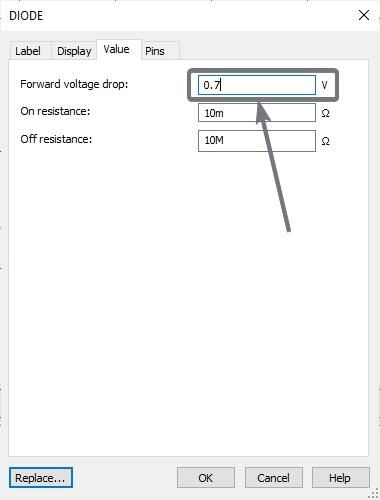
However, you can even remove the inaccuracies like, remove the 0.7 Volt voltage drop and change it to an ideal diode, just in case you need it under certain circumstances.
When you are actually making an electronic circuit, there are different things that come into play, which include, the resistance of the wires that you are using, connection faults, temperature differences, and many other things.
Hence, Multisim is the perfect tool to find whether your circuit is overall functional. Multisim is however only available for Windows, which is kind of disappointing for Linux and macOS users.
So that was all about how you can install and use Multisim on your computer. Do you have any questions? Feel free to comment on the same below.
Other Articles to read:
Related Posts
What is a juice-jacking attack? How can we be safe from such attacks?
Getting the right dashcam for your needs. All that you need to know
WhatsApp iPad App Gets Major Overhaul, Adds New Communities Feature
Moto G85 5G launched in India but is unlikely to beat VIVO or XIAOMI
Rise of deepfake technology. How is it impacting society?
Smartphone Apps Get Smarter- Meta AI’s Integration Across Popular Platforms